

There are numerous high-brightness leds:
12 blue leds mounted on the acrylic separator plate pointing upwards;
12 blue leds mounted on the acrylic separator plate pointing downwards;
12 red leds mounted on the acrylic separator plate pointing upwards;
4 blue leds illuminating the base of the dummy hard drive;
20 blue leds inside the dummy hard drive (16 to animate it, simulating rotation)
2 green leds are mounted on the dummy drive arm itself (the arm and its leds move when controlled)
In addition there are 16 superflux (three chip) leds:
8 superflux blue leds on the acrylic separator plate pointing up (these can simulate rotation).
8 superflux red leds on the acrylic separator plate pointing down (separated into left hand and right hand groups).
Following are some aspects of how this was achieved.
1) Create the nurons
Everyone (including me) seems to like the idea of the 'guts' of the project being on display. Hence, the leds and their wiring are on-show. (Some very messy bits are hidden away.)

24 leds being added to the main acrylic plate.


Blues are wired in pairs with a resistor
Reds are wired in threes (they run on a lower PD)
Every led in the brain runs at a current of around 20mA which is below their maximum value (usually 30mA).

The downward-pointing leds installed with their wiring.
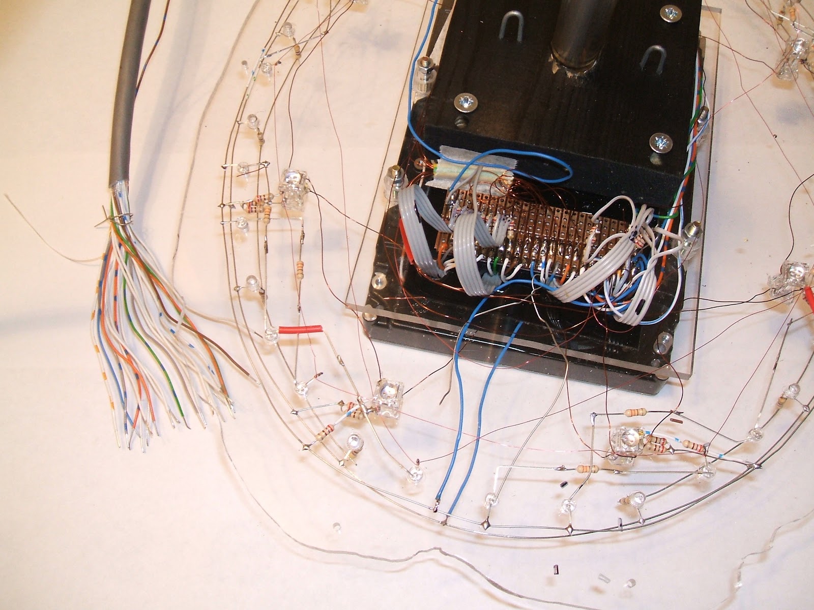
The 'spinal cord' is a 24 wire cable which runs inside the supporting acrylic tube. The next photo shows the main plate with all of its leds wired-up and the 24 control cables fanning out from the acrylic tube.

2) Modify the dummy hard drive
The dummy hard drive was also has lots of wires.


The hard drive has 17 pins for electrical connections:


Keeping a note of things, helps later!
Some connecting leads were made:

3) Bring all the elements together

Add a copper circuit board to link the wires from the leds to the wires of the spinal cord


Start creating some order from the chaos, by soldering the 24 wires from the spinal cord onto the circuit board


4) Assemble the finished brain module and 'fire it up'.
The results are excellent. There is plenty of 'fire power' so that it should be clearly visible on the brightest of days. In dull conditions it looks stunning.
Photographing it is difficult due to the huge dynamic range (brilliant blues and brilliant reds).
Note: the wooden base is just for a manufacturing support


Top half blue, bottom half red.


Controlling electronics next......
No comments:
Post a Comment