Saturday, August 18, 2012

"The Brain": Step 6 - Main controlling electronics

To control what the brain does when a file is accessed, is achieved using a PIC microcontroller mounted on a custom designed printed circuit board (PCB).The end result looks like this:


This design will probably use a 'master' board plus two or three identical electronic control boards (depending on how much control is to be achieved).
Some of the main stages in producing a control board are described below:

1) Design the circuit
This starts on the back of an envelope and on a prototyping platform (a 'breadboard').

It progresses to designing a schematic diagram on an electronics CAD/CAM suite (I use KiCAD).

The final schematic looks like this

Key features are:

  • Lots of flashing LEDs on the board itself!
  • 11 high-current channels of LED control
  • Programmable
  • Some user-control using two jumpers

2) Pick the actual electronic components
Tell the CAD/CAM software what components are available for the circuit. For example, the main 'spinal cord' wires will be connected using several 3-way screw-terminals. In order to produce a PCB, the software needs to know the exact dimensions of the component, so it can lay-out the correct copper pads.
3-way connector details

3) Design the PCB
Decide on the board size. Drop the component 'footprints' onto the board. Slowly make each connection from pad to pad, until the whole schematic diagram is correctly wired-up.
Wiring-up the pads

The finished board design
4) Etch and drill the PCB
The design is printed and then transferred optically (using a UV light box), to a light-sensitive layer on a new PCB.

The optical image is developed (much like an old 'wet' photograph negative).

Copper is exposed ready to be etched away

The board is then immersed in an acid etching bath.
Etching starting

Etching nearly finished
The finished board:

The holes are then drilled:

Top of the finished board

Bottom of the finished board

5) Solder on the components
Add each component
Components being added

The finished board

The finished board
6) Program the micro-controller
The board does nothing until the micro-controller is 'told' how to control the outputs. This is done using a programming language on a PC, with the finished software being saved on the micro-controller, by connecting the PCB to the PC using the special programming port (the white, 6-pin plug).

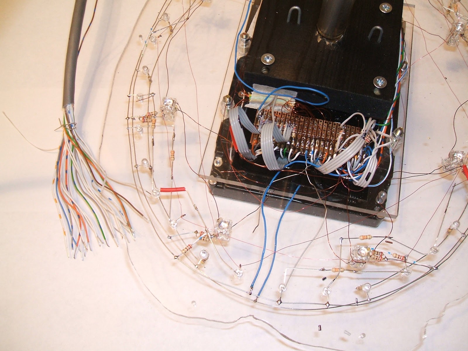
7) Finally, see if it works!
Hopefully, if every step has been fault-free, everything will work as it is supposed to. The spinal cord is connected up, so is the power supply. A simple, test program is installed and the brain is switched on.

The software lights up the bottom half of the brain like a 'pulse' and continually animates the rotation of the dummy hard drive.

The infant brain is born!

Next: Add some more of the brain LED channels to the existing control PCB and adjust the software to make the brain react to a signal (the accessing of the real hard drive).

Tuesday, August 14, 2012

"The Brain": Step 5 - Light up the nurons


To indicate when a file from the brain is being accessed, it will light up. To make the access 'events' more interesting, various lighting effects will be produced using microcontrollers. In order to achieve this, a total of 78 leds are included inside the brain in 23 control groups (16 groups are for simulating rotation).

There are numerous high-brightness leds:
12 blue leds mounted on the acrylic separator plate pointing upwards;
12 blue leds mounted on the acrylic separator plate pointing downwards;
12 red leds mounted on the acrylic separator plate pointing upwards;
4 blue leds illuminating the base of the dummy hard drive;
20 blue leds inside the dummy hard drive (16 to animate it, simulating rotation)
2 green leds are mounted on the dummy drive arm itself (the arm and its leds move when controlled)

In addition there are 16 superflux (three chip) leds:
8 superflux blue leds on the acrylic separator plate pointing up (these can simulate rotation).
8 superflux red leds on the acrylic separator plate pointing down (separated into left hand and right hand groups).

Following are some aspects of how this was achieved.

1) Create the nurons
Everyone (including me) seems to like the idea of the 'guts' of the project being on display. Hence, the leds and their wiring are on-show. (Some very messy bits are hidden away.)
24 leds being added to the main acrylic plate.


Blues are wired in pairs with a resistor
Reds are wired in threes (they run on a lower PD)

Every led in the brain runs at a current of around 20mA which is below their maximum value (usually 30mA).


The downward-pointing leds installed with their wiring.

The 'spinal cord' is a 24 wire cable which runs inside the supporting acrylic tube. The next photo shows the main plate with all of its leds wired-up and the 24 control cables fanning out from the acrylic tube.

2) Modify the dummy hard drive

The dummy hard drive was also has lots of  wires.


The hard drive has 17 pins for electrical connections:

Keeping a note of things, helps later!
Some connecting leads were made:


3) Bring all the elements together


Add a copper circuit board to link the wires from the leds to the wires of the spinal cord


Start creating some order from the chaos, by soldering the 24 wires from the spinal cord onto the circuit board
Then slowly start to add the wires from the leds
Eventually, all of the connections are made and all aspects of the brain can be controlled via its spinal cord.

4) Assemble the finished brain module and 'fire it up'.
The results are excellent. There is plenty of 'fire power' so that it should be clearly visible on the brightest of days. In dull conditions it looks stunning.

Photographing it is difficult due to the huge dynamic range (brilliant blues and brilliant reds).
Note: the wooden base is just for a manufacturing support


Top half blue, bottom half red.


Controlling electronics next......

Saturday, August 11, 2012

"The Brain": Step 4 - More brain mounting stuff

One of the hassles is the fact that having chosen to support the brain on an acrylic tube, all of the wiring will have to come up inside the tube. This sounded like a good idea at the start, however this 'spinal cord' of wires will be wired-in at both ends during the development of the electronics and it will not be easy to work on the support/mounting once the electronics has started.

Consequently, the support system might just as well be done up-front, so the look-and-feel of the brain can be judged as the electronics is developed.

The final brain will be supported on an acrylic plinth. The top-plate of the plinth will have to have a hole for the electronic 'spinal cord' to pass through. The electronics will be on display inside the plinth, near the top.

The mount for the brain will be another hard drive, suitably modified.

The finished components are shown below


 The mounting has to support  the acrylic tube at an angle of 20 degrees, and be strong. A brass casting and a copper plumbing fitting were cut at the correct angles and soldered together. The hard drive was gutted and holes drilled and tapped to hold the casting.

The casting can bee seen from the underside - also the hacked PCB which leaves the header plugs visible from the outside (on the left of the photo), but not in the way of the assembly.

The housing then covers the casting.

And the olive and nut go over the top.

The system works well and looks good.


Note - top half of the brain is still un-trimmed
This will sit (be bolted) onto the top of the plinth, the 'spinal cord' will pass through the acrylic tube into the plinth.

For now, it is mounted on a wooden board, with space for the 'spinal cord' to come out from under it and be connected to the electronics.